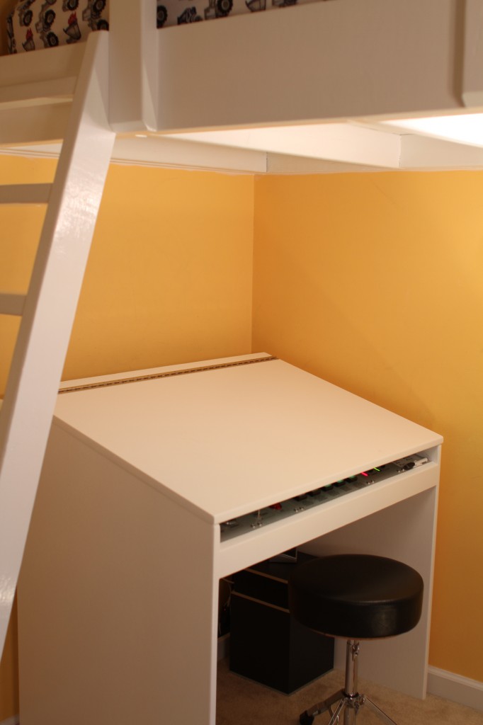
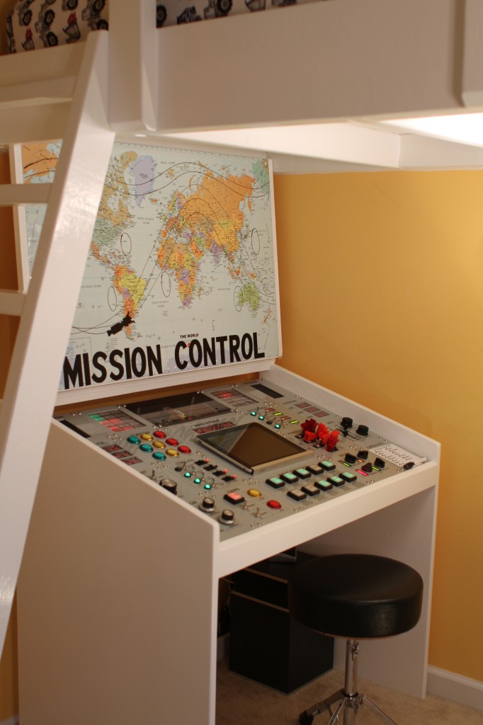
| Some parents take the carrot approach to homework enforcement, others the stick. This is the best carrot I’ve ever seen. Some world-class parenting skills are on display right here. This is the homework desk of Jeff Highsmith’s older son: And this is what it looks like when he’s finished his homework and is allowed to raise the lid. The desk came about as the result of a family visit to the Kennedy Space Center. It’s not an exact facsimile of an Apollo Mission control desk (the real ones don’t make whooshy fizzy rocket noises, deep mechanical clankings and exciting beepings, and, as Jeff says, they do more monitoring than controlling), but those of you who have seen the real thing will definitely recognise what this is based on. Here is a wonderful, wonderful how-to video which walks you around the build and the finished desk. We love the clear panel to display the Pi and the Arduino! (Eben got to the bit in the video where Jeff’s son issues the command to stir the oxygen tanks and shouted: “NOOOOOOO!”) The whole thing is run on a Raspberry Pi and Arduino, working together. Jeff says:
It even plays real clips from the real Apollo 11 mission, which Jeff was able to source online. You can read much more about the build, what all those wonderful switches and dials do in Jeff’s article for MAKE. Jeff, I hope you’re at the big Maker Faire Bay Area this May. We’re sending our education team, and they’re big fans; they’d like to pick your brains! |
A Semi-automated Technology Roundup Provided by Linebaugh Public Library IT Staff | techblog.linebaugh.org
Tuesday, February 25, 2014
Mission Control desk
Subscribe to:
Post Comments (Atom)


No comments:
Post a Comment