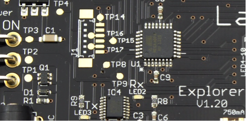
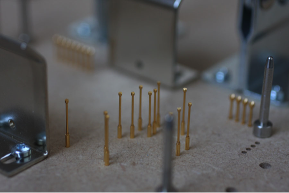
| A lot of companies are building Raspberry Pi add-ons – Raspberry Pi accessory businesses have been called out by the UK Telegraph this year as one of their top 2014 startup investments. It gives us enormous pleasure to watch people build jobs and businesses around the Raspberry Pi, and we watch the numerous companies which add to the ecosystem with great interest. Laika Explorer was a successful Kickstarter last year, which promised a powerful robotics controller for the Pi, controlled with Scratch or Python. Last week I had mail from Andy Bakin, who has allowed us to share how he’s expanding production – and how he’s using a Raspberry Pi as part of his test rig (something we’re seeing an increasing number of factories doing; even the factory that builds Raspberry Pis tests them using a Pi now). Over to Andy! Testing Times I am pleased to say that the Laika Explorer is moving into its second production run: this time we are making 1000 units. This is great news but as production volumes ramp up, the efficiency of manufacturing has to increase. The first 500 units were individually inspected, programmed, and tested by hand. This took a long time and used up a fair share of my Sunday evenings when I should have been resting, sipping a glass of red and catching an episode of Breaking Bad in preparation for the week ahead. And so the need for a production tester is a priority as I move towards receiving that box of 1000 Explorers. Now I have made quite a few production test jigs in the past when moving previous designs into manufacture. They have always been custom builds with the test program running as firmware on a bespoke PCB. This is fine if the product is stable and is not set to change much. It is also fine if you do not plan to release many new designs which will each require their own specific test equipment. The nice thing about this approach is that the test equipment can be neatly self-contained in a box, stored easily and grabbed off the shelf when needed. The problem arises when the product being tested has new functionality which needs testing and therefore requires the test jig program to be updated. Not a huge issue but it does require getting to the test jig and 'flashing' the new firmware to incorporate new test routines. There are concerns from a hardware point of view too as most of the test jigs I have made use a customised PCB of some kind which makes it hard to quickly put together another jig if you want to double your testing capacity. Now, the Explorer is the first in what will be a range of products all designed to work together. Up to 32 different modules will be made, which means that I need a test set-up that can easily be replicated, updated and switched between designs depending on which one is coming off the production line. I also want to be able to get remote access to the test equipment, which will be used at the manufacturers, so I can update and add test routines from the convenience of my office and keep an eye on the pass/fail rate to quickly respond to any problems. Let's Get Jiggy With It! The solution is to run the test software on a networked Raspberry Pi connected to a Laika Explorer which is housed inside a test fixture. The test fixture and test software is unique to each design as electrical connections have to be made to the PCB test points, and, of course, the test algorithm will be different for each device being tested. As the Laika uses USB it will be easy to swap the test jig hardware when a different product needs testing. The test program can very easily be selected using the software. Probe-ably For The Best We begin with a PCB design, in this case done in Eagle, which is used to create a .dxf file (this is an industrial format for use by CNC milling machines) containing the different layers of the board. The dxf file was then opened in a CAD program and a new layer created which would be used by the CNC machine to drill holes in a piece of 12mm MDF perfectly in line with the test points on the PCB. Here are some of the test points on the Explorer labelled TP1, TP2 etc.
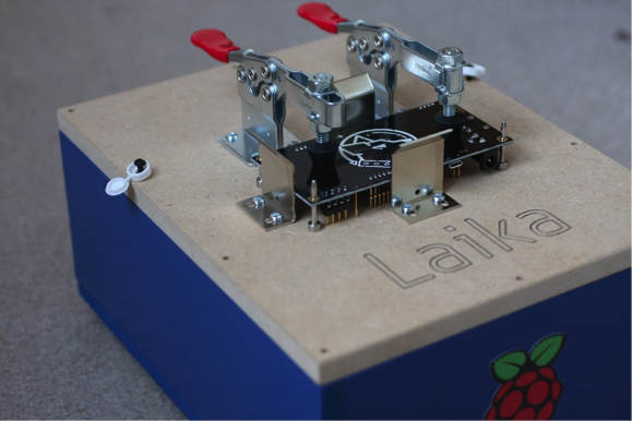
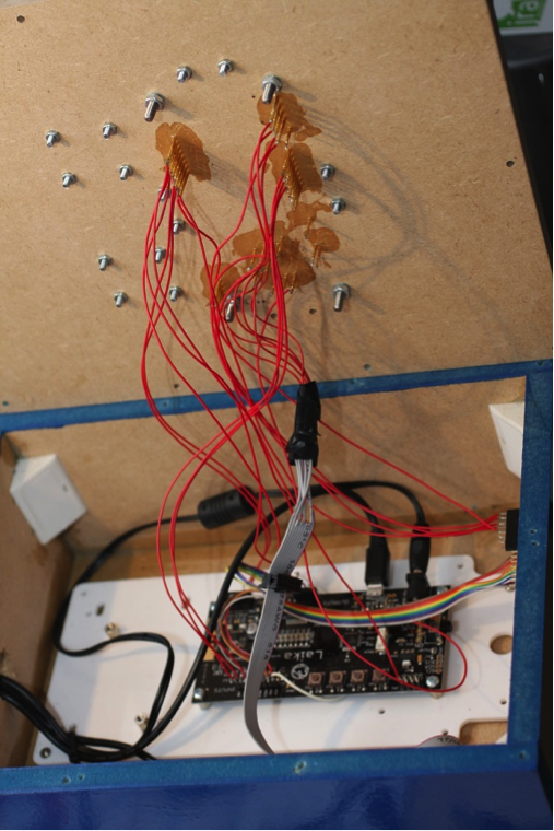
The Hardware Here is the Explorer in place on the jig:
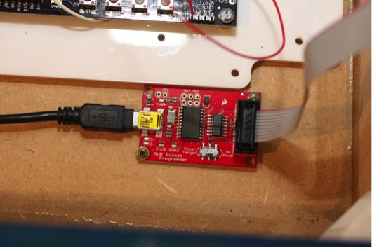
I have taken the decision to program firmware on the Explorer as they come off the production line. The alternative is to have them programmed before being placed on the board but that means it is more difficult to update the firmware if I need to. After a period of time I may decide that the firmware is not going to change and move to this method of programming as it might be quicker, but for now I like the flexibility of post-production programming, and it's pretty quick any way. To program these devices I have used an AVRDUDE connected directly to the RPi:
This is the best part of this project as the result is a simple graphical user interface which anyone can use to program and test a PCB. All the user has to do is click 'RUN' and the Python script uses the AVRDUDE to program the Explorer's Atmel chip, and then check all functions of the device under test by reading in voltages. This was the purpose of this project: to create a 'red light/green light' tester which either indicates a 'pass' or a 'fail'. In the case of a fail, details will be given as to the error found and the information logged for record keeping, and downloading by me remotely. Two Explorers: One Pi To use an Explorer to effectively test another Explorer meant I had to add some functionality to the Laika drivers so that more than one board can be plugged into the Raspberry Pi without conflict, and be independently controlled. By giving the test jig Explorer a different USB device descriptor, I was able to write software which could differentiate the two Explorers on the same USB connection. This opens up the possibility of connecting many Explorers all on the same USB. GUI The GUI was designed in Glade and Gtk+3 was used to interface to Python. This is a great way of creating an event driven program to control the test jig. As Laika can easily be controlled through Python, it was quite straightforward to build the test jig software. It Came To Pass Hopefully most of the Explorers off the production line will pass these production tests without any issues, but inevitably there will be the odd one that doesn't for some reason. This is expected and target failure rates are typically around 1% for builds of this size. The important thing is to detect these failures and extract the problematic PCB from the batch. For low-cost designs being manufactured in millions as opposed to thousands, then testing in this way becomes far too time consuming and would probably cost more in time and labour than the product itself. In this case the production is so finely tuned that the failure rate becomes more like 0.1% and the fact that someone will occasionally receive a defective piece of electrical equipment is accepted- we've all been that 0.1% at some point I'm sure. |
A Semi-automated Technology Roundup Provided by Linebaugh Public Library IT Staff | techblog.linebaugh.org
Wednesday, January 29, 2014
Laika Explorer: what it’s like to build a Raspberry Pi accessory startup
Subscribe to:
Post Comments (Atom)



No comments:
Post a Comment