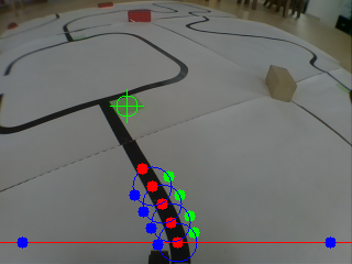
| Helen: Today we’re delighted to have a guest post from 17-year-old student Arne Baeyens, aka Robotanicus, who has form in designing prize-winning robots. His latest, designed for the line-following challenge of a local competition, is rather impressive. Over to Arne… Two months ago, the 24th of May, I participated in the RoboCup Junior competition Flanders, category 'Advanced Rescue'. With a Raspberry Pi, of course – I used a model B running Raspbian. Instead of using reflectance sensors to determine the position of the line, I used the Pi Camera to capture a video stream and applied computer vision algorithms to follow the line. My robot wasn't the fastest but I obtained the third place. A short video of the robot in action: In this category of the RCJ competition the robot has to follow a black line and to avoid obstacles. The T-junctions are marked by green fields to indicate the shortest trajectory. The final goal is to push a can out of the green field. 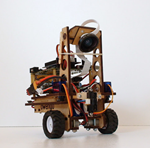 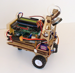 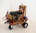 This is not my first robot for the RCJ competition. In 2013 I won the competition with a robot with the Dwengo board as control unit. It used reflectance and home-made colour sensors. The Dwengo board uses the popular pic18f4550 microcontroller and has amongst other functionalities a motor driver, a 2×16 char screen and a big, 40pin extension connector. The Dwengo board is, like the RPi, designed for educational purposes, with projects in Argentina and India. As the Dwengo board is a good companion for the Raspberry Pi, I decided to combine both boards in my new robot. While the Pi does high-level image processing, the microcontroller controls the robot. The Raspberry Pi was programmed in C++ using the OpenCV libraries, the wiringPi library (from Gordon Henderson) and the RaspiCam openCV interface library (from Pierre Raufast and improved by Emil Valkov). I overclocked the Pi to 1GHz to get a frame rate of 12 to 14 fps. Using a camera has some big advantages: first of all, you don't have that bunch of sensors mounted close to the ground that are interfering with obstacles and deranged by irregularities. The second benefit is that you can see what is in front of the robot without having to build a swinging sensor arm. So, you have information about the actual position of the robot above the line but also on the position of the line in front, allowing calculation of curvature of the line. In short, following the line is much more controllable. By using edge detection rather than greyscale thresholding, the program is virtually immune for shadows and grey zones in the image. If the line would have had less hairpin bends and I would have had a bit more time, I would have implemented a speed regulating algorithm on the base of the curvature of the line. This is surely something that would improve the performance of the robot. I also used the camera to detect and track the green direction fields at a T-junction where the robot has to take the right direction. I used a simple colour blob tracking algorithm for this. A short video of what the robot thinks: Please note that in reality the robot goes a little bit slower following the line. Different steps of the image processing Image acquired by the camera (with some lines and points already added): The RPi converts the colour image to a greyscale image. Then the pixel values on a horizontal line in the image are extracted and put into an array. This array is visualized by putting the values in a graph (also with openCV): From the first array, a second is calculated by taking the difference from two successive values. In other words, we calculate the derivative: An iterating loop then searches for the highest and lowest value in the array. To have the horizontal relative position of the line in the array, the two position values—on the horizontal x axis in the graphed image—are averaged. The position is put in memory for the next horizontal scan with a new image. This makes that the scan line does not have to span the whole image but only about a third of it. The scan line moves horizontally with the centre about above the line. But this is not enough for accurate tracking. From the calculated line position, circles following the line are constructed, each using the same method (but with much more trigonometry calculations as the scan lines are curved). For the second circle, not only the line position but also the line angle is used. Thanks to using functions, adding a circle is a matter of two short lines of code. The colour tracking is done by colour conversion to HSV, thresholding and then blob tracking, like explained in this excellent video. The colour tracking slows the line following down by a few fps but this is acceptable. 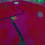  As seen in the video, afterwards all the scan lines and some info points are plotted on the input image so we can see what the robot 'thinks'. And then? After the Raspberry Pi has found the line, it sends the position data and commands at 115,2 kbps over the hardware serial port to the Dwengo microcontroller board. The Dwengo board does some additional calculations, like taking the square root of the proportional error and squaring the 'integral error' (curvature of the line). I also used a serial interrupt and made the serial port as bug-free as possible by receiving each character separately. Thus, the program does not wait for the next character while in the serial interrupt. The Dwengo board sends an answer character to control the data stream. The microcontroller also takes the analogue input of the SHARP IR long range sensor to detect the obstacles and scan for the container. In short, the microcontroller is controlling the robot and the Raspberry Pi does an excellent job by running the CPU intensive line following program. There's a post on the forum with a more detailed technical explanation – but you will find the most important steps below. Electrical wiring Grippers Building the robot platform This time, I took a different approach. Instead of using an outer shell (like insects have), I made a design that supports and covers the parts only where necessary. The result of this is not only that the robot looks much better, but also that the different components are much easier to mount and that there is more space for extensions and extra sensors. The design files can be found here: Robot RoboCup Junior – FabLab Leuven. 3D renders in SketchUp: 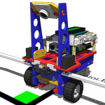 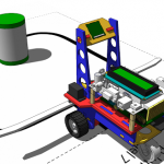 On the day of the RCJ competition I had some bad luck as there wasn't enough light in he competition room. The shutter time of the camera became much longer. As a consequence, the robot had much more difficulties in following sharp bends in the line. However, this problem did not affect the final outcome of the competition. Maybe I should have mounted some LEDs to illuminate the line… |
Thursday, August 7, 2014
An image-processing robot for RoboCup Junior
Subscribe to:
Post Comments (Atom)
No comments:
Post a Comment