| Just over two weeks ago, we announced the new Raspberry Pi B+ with immediate availability. We’ve been very pleased at the response from the community and press about the B+, and most people seem to appreciate why we decided to evolve the Model B in the way we did – lots of you have been in touch to tell us how much you’re enjoying your new B+. There are many great new features built into the B+, but today we want to talk about one new feature we are particularly excited about. One of the brilliant things about the Raspberry Pi has always been the ability to attach physical hardware to the Raspberry Pi’s GPIO (General Purpose Input/Output) connector. There are so many third party add-on boards that attach to the raspberry Pi and extend its functionality: motor controllers, LEDs, buttons, sensors, microcontrollers, LCDs, ADCs and DACs; you name it, someone has almost certainly created an add-on board that makes it usable with the Raspberry Pi. 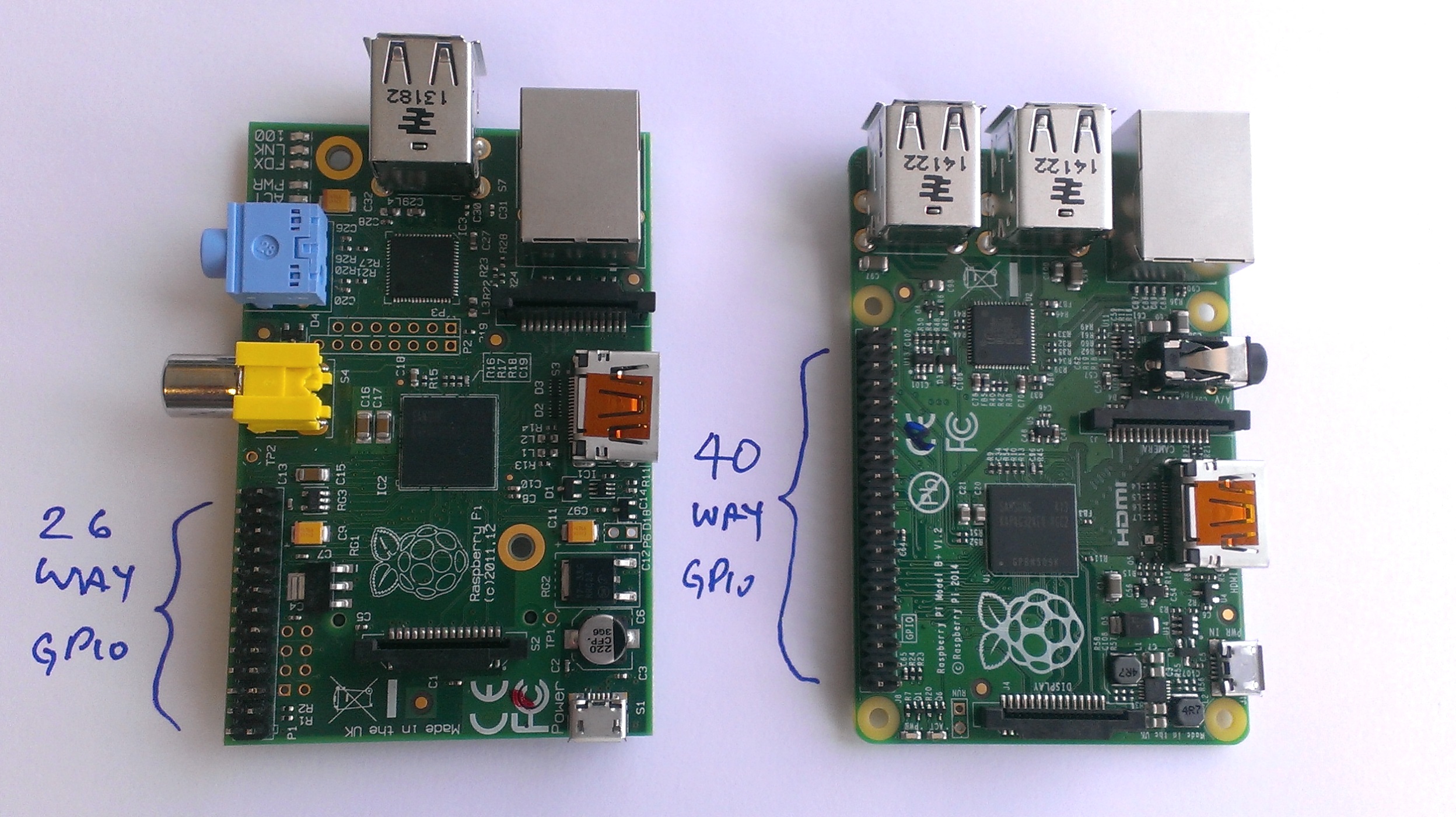 Model B’s 26W vs Model B+’s 40W GPIO connectors On the Raspberry Pi models A and B, the GPIO connector has 26 pins. Users attaching an add-board to the model A or B Pi usually have to work out which drivers are required for their specific board, and then edit the relevant Linux files to make them load at boot time before the board is usable (or load them by hand from the command line). The Raspberry Pi has no knowledge of whether it has a board attached or not, and the various drivers, when loaded, will simply assume that they can make exclusive use of the GPIO interface. Most of the time this all works OK, but it can be a bit challenging for new users. Linux drivers blindly assuming GPIO pins are available can also occasionally cause confusion. The Raspberry Pi B+ has been designed specifically with add-on boards in mind and today we are introducing ‘HATs’ (Hardware Attached on Top). A HAT is an add-on board for B+ that conforms to a specific set of rules that will make life easier for users. A significant feature of HATs is the inclusion of a system that allows the B+ to identify a connected HAT and automatically congifure the GPIOs and drivers for the board, making life for the end user much easier! Before we go any further, it is worth noting that there are obviously a lot of add-on boards designed for the original model A and B boards (which interface to the original 26 way GPIO header). The first 26 pins of the B+ GPIO header are identical to those of the original models, so most existing boards will still work. We are not breaking compatibility for existing boards; we’re creating a specification that B+ add-on board designers can follow (if they so wish), which is designed to make end users’ lives much easier. So what is a HAT? 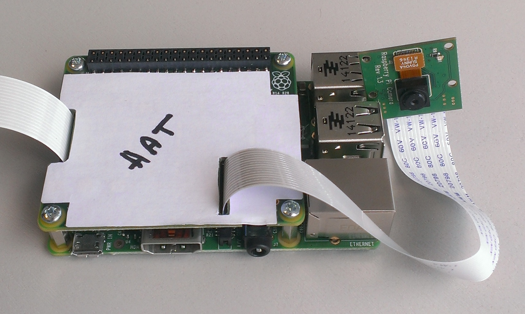 B+ sporting a (mehcanical sample of a) HAT and showing camera and display connections In a nutshell a HAT is a rectangular board (65x56mm) that has four mounting holes in the (nicely rounded) corners that align with the mounting holes on the B+, has a 40W GPIO header and supports the special autoconfiguration system that allows automatic GPIO setup and driver setup. The automatic configuration is achieved using 2 dedicated pins (ID_SD and ID_SC) on the 40W B+ GPIO header that are reserved for an I2C EEPROM. The EEPROM holds the board manufacturer information, GPIO setup and a thing called a ‘device tree‘ fragment – basically a description of the attached hardware that allows Linux to automatically load the required drivers. What we are not doing with HATs is forcing people to adopt our specification. But you can only call something a HAT if it follows the spec. So why are we bothering with all this? Basically, we want to ensure consistency and compatibility with future add-on boards, and to allow a much better end-user experience, especially for less technically aware users. The HAT specification is available on GitHub for those wishing to design add-on boards for the B+. As previously explained, there is no requirement to follow the HAT specification, but we encourage people to think about following it if possible, as it will make the world a better place for end users. One final bit of good news: we have used a surface mount connector on our internal prototype HAT which works very nicely. As you can see from the pictures it solders to the top of the board and then fits over an extension header (the extension header pins push through the HAT from underneath). As the extension headers push through like this it is possible to either use a short, flush mounting extension or a version with longer pins that poke out above the HAT and allow further access to the GPIO pins for debugging.  HAT using extender with longer pins For HAT designers wanting to use these connectors, we have secured discounted pricing through Toby Electronics. The connector part numbers are:
Toby tell us they are getting stock in now, which should arrive for the 5th August. Please post technical questions about the specification to the forum. |
Thursday, July 31, 2014
Introducing Raspberry Pi HATs
Subscribe to:
Post Comments (Atom)
No comments:
Post a Comment